The FPGA:
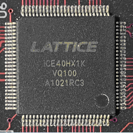
This board uses the Lattice iCE40 HX1K (the 1K in its name refers to 1280 Logic Cells, each Cell contains a 4-input LUT and d-flip-flop):- Device Family: iCE40
- Device: HX1K
- Device Package: VQ100
Lattice Semiconductor:
-
Lattice Semiconductor (NASDAQ: LSCC) is the "low power programmable leader."
Headquaters are in Hillsboro, Oregon.

Demo Program
This dev board comes with a demo program to test out the peripherals. This program can be downloaded from Nandland.com (a bitmap FPGA image in the form of a .bin file):
The Demo program does the following:
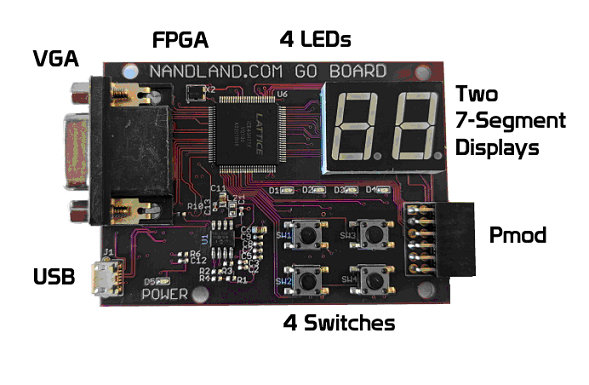
- The board is powered by connecting it to a host computer (micro-USB to the board, and USB-A on the host side). The green power light on the board should light up.
- Each of the push buttons individually lights up a different LED.
- Push button 1 will start a demo of the two 7-segment displays, lighting up the various segments.
- Launching a terminal emulator like Tera Term will establish a UART connection to the board, and the demo program will accept keyboard input from the host, send it to the FPGA, and return each character to the host to be displayed in the terminal emulator.
- The VGA connector can be connected to a VGA monitor, and test patterns can be displayed using the keyboard numeric keys.
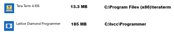
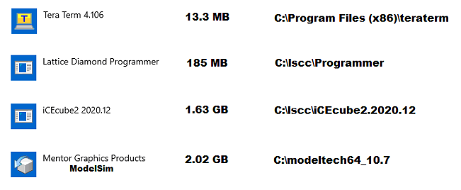
Setting up the Programmer Tool
In order to get the .bin program onto the Go Board, a subset of the toolchain needs to be installed. The Diamond Programmer needs to be installed in order to program the FPGA from the .bin file. Tera Term is needed to interact with the demo program:
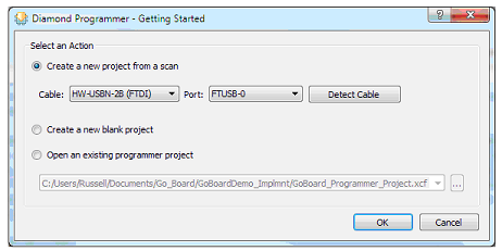
- The Go Board has an IC that converts the micro-USB port into an SPI interface.
- The program is stored onboard in Flash memory. The FPGA boots up from Flash memory.
- Since an SPI interface is being used, the Diamond Programmer won't be able to detect the cable:
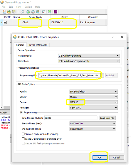
- After selecting OK, select the Device Family and Device, as well as navigating to the downloaded .bin file and set the following additional settings:
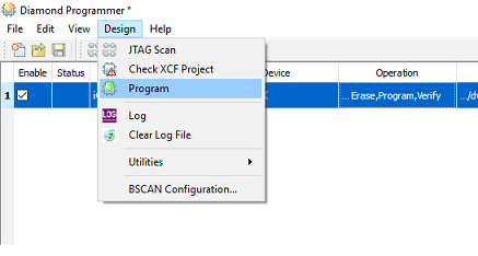
- Click OK and then select Deisgn -> Program
Running the Demo
- Pressing each of the 4 push buttons will light up a different LED.
- Pressing push button 1 will also launch the two 7-segment displays demo
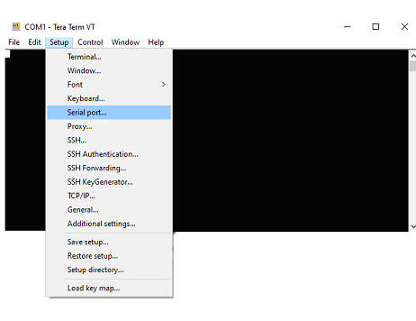
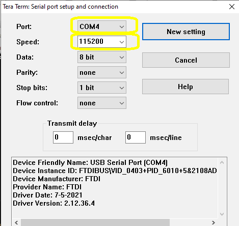
- Launch Tera Term on the host computer and configure the serial port
- Typing on the host computer's keyboard will send the characters to the FPGA demo program, and it will send it back to the host to be displayed on the terminal emulator's screen.
- Connect a VGA monitor to the Go Board and press keys 1-5 to see different test patterns on the screen

Setting up the Full Toolchain
The full toolchain for the Lattice iCE40 HX1K involves the following tools:- design entry
- simulation
- synthesis
- place & route
- bitstream generation
- programming
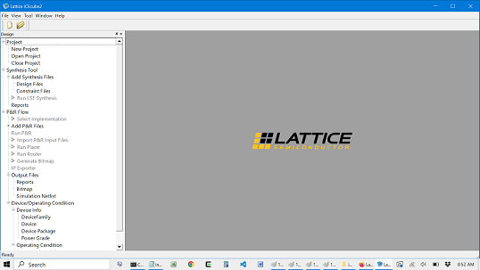
- design entry [Lattice iCEcube2]
- simulation [Siemens ModelSim]
- synthesis [Lattice iCEcube2]
- place & route [Lattice iCEcube2]
- bitstream generation [Lattice iCEcube2]
- programming [Lattice Diamond Programmer]
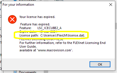
The Lattice iCEcube2 IDE requires a license, which (at the time of this writing) is freely available for "hobbyists", though it still expires and is quite a pain to renew. If you start iCEcube2 and receive the following popup, it's time to renew:
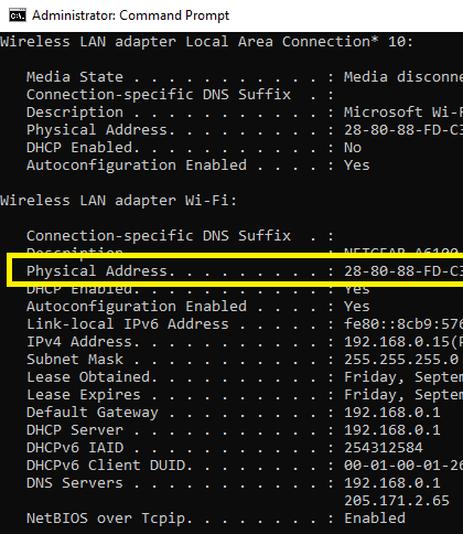
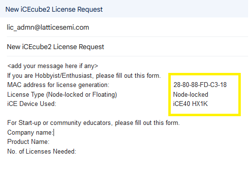
- Find the MAC address for your network interface by opening a command line and running "ipconfig /all"
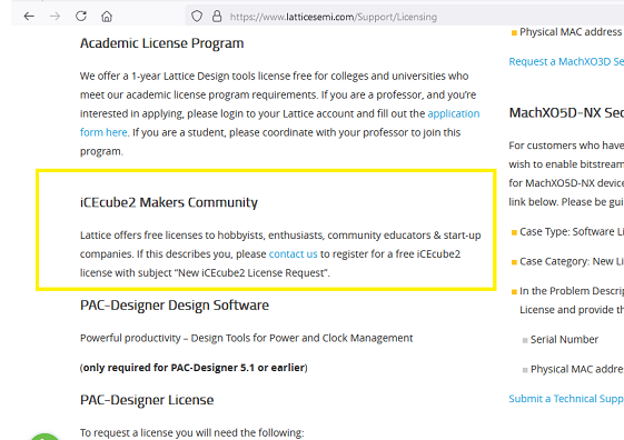
- Look on the Lattice website for instructions on how to obtain a free license
- Write the following email
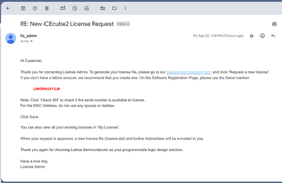
- Eventually you'll receive the following email:
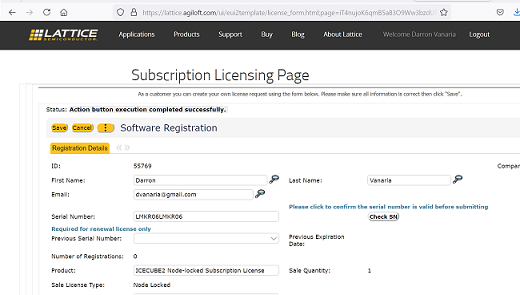
- Follow the link to the Subscription Licensing Form
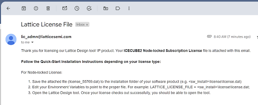
- They'll send you the .dat file in another email, along with instructions on where to "install" the license (i.e. where to put the .dat file on your system)
- Opening iCEcube2 should now be successful
- Since this license (.dat file) is stored locally on your machine (C:\licenses\FlexLM), and it's tied to your particular machine's MAC address, you'll have to download/install a different license for each machine you plan to develop on.
VHDL Overview
VHDL (VHSIC Hardware Description Language) is a hardware description language that can model the behavior and structure of digital systems at multiple levels of abstraction, ranging from the system level down to that of logic gates, for design entry, documentation, and verification purposes.
The language was developed for the US military VHSIC program in the 1980s, and has been standardized by the Institute of Electrical and Electronics Engineers (IEEE) as IEEE Std 1076.
The Very High Speed Integrated Circuit (VHSIC) Program was a United States Department of Defense (DOD) research program that ran from 1980 to 1990. Its mission was to research and develop very high-speed integrated circuits for the United States Armed Forces.
Overview of VHDL Syntax
-
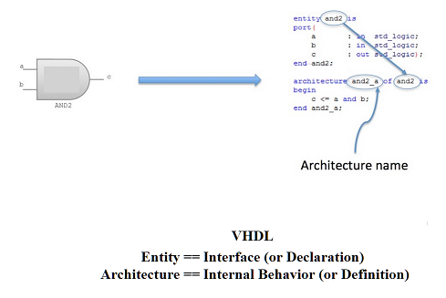
The two parts to a VHDL file (.vhd) are
- entity (declares the inputs and outputs of the module)
- architecture (defines how those inputs are processed to produce
the output)
- The architecture name is bound to a particular entity name, even though it's recommended to only define one architecture per entity, and only one entity-architecture pair per .vhd file!
- Instead of a port() list, the defintions (behavior) is defined
within a begin-end block. The entity section has the "end" keyword
too, but no "begin", so really the only difference is that instead
of
-
port( ... );
-
begin ...
- Project 1 (Push button to control LED)
- Project 2: Implement an AND Gate with a Look Up Table (LUT)
- Project 3: Register (D-Flip-Flop) to implement State Machine
- Project 4: Mechanical Bouncing and In-Circuit Debounce
- Project 5: How to Drive a 7-Segment Display
For the entity part, each "pin" is declared as a specific type (usually of type "std_logic") as well as a direction (in/out) of the data flow. And each pin is also assigned a name.
-
This is all declared inside a port() list (looks like a C function call).
-
Each pin has a name, data direction, and type
All pins are declared inside a port() list. This is similar to a C function call, except each pin is separated by ; instead of ,
-
port (
-
i_Switch_1 : in std_logic;
i_Switch_2 : in std_logic;
i_Switch_3 : in std_logic;
i_Switch_4 : in std_logic;
o_LED_1 : out std_logic;
o_LED_2 : out std_logic;
o_LED_3 : out std_logic;
o_LED_4 : out std_logic
);
The port list is contained within the entity declaration:
-
entity p1 is
-
port();
The architecture section follows a similar syntax, except:
-
architecture RTL of p1 is
begin
-
o_LED_1 <= i_Switch_1;
o_LED_2 <= i_Switch_2;
o_LED_3 <= i_Switch_3;
o_LED_4 <= i_Switch_4;
Here is VHDL in a nutshell (file e.vhd):
-
entity e is
- port (
- in1 : in std_logic;
in2 : in std_logic;
out : out std_logic
architecture a of e is
-
begin
-
out <= in1 and in2;
Another VHDL example:
Yet another:
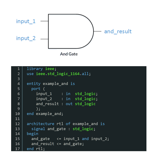
You can see in that last example (syntax highlighted in green) the necessary library to include, in order to access the datatype "std_logic"
PROJECTS (from Nandland.com)
There are 10 projects from Russell Merrick's website (Russell is the designer and creator of the Nandland Go board) that run through the fundamental concepts of FPGA programming. His website and tutorials are highly recommended!
The following are my own notes and interpretation of his tutorials. For many of the easier designs, they follow his tutorials fairly closely, but for some of the more complex desings (specifically the VGA implementation) I have come up with my own interpretations and designs.
The following are my notes and source code for each project.