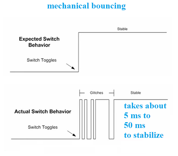
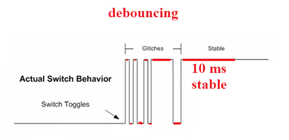
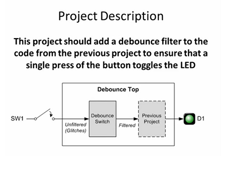
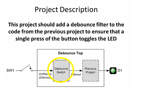
We could introduce a new component (a black box) in FRONT of the design
that was used in Project 3, one that takes in the Button 1 signal and
waits for the signal to stablize for 10 ms (either high for 10 ms or
low for 10 ms). Once stable, it could send this signal along to the
rest of the circuit.
To implement this new component, a COUNTER will be needed, which is
going to have to be precisely linked to the external 25 MHz clock. We
need a counter that will look at the signal of Button 1, and start
counting if the signal doesn't change for a bit - if it reaches 10 ms,
it will pass that signal along. If the
signal changes before then, it will reset to 0 and start counting again.
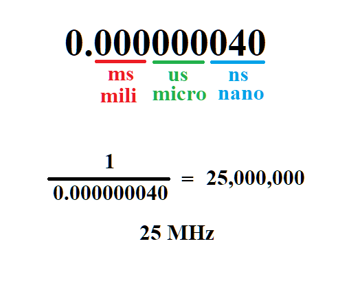
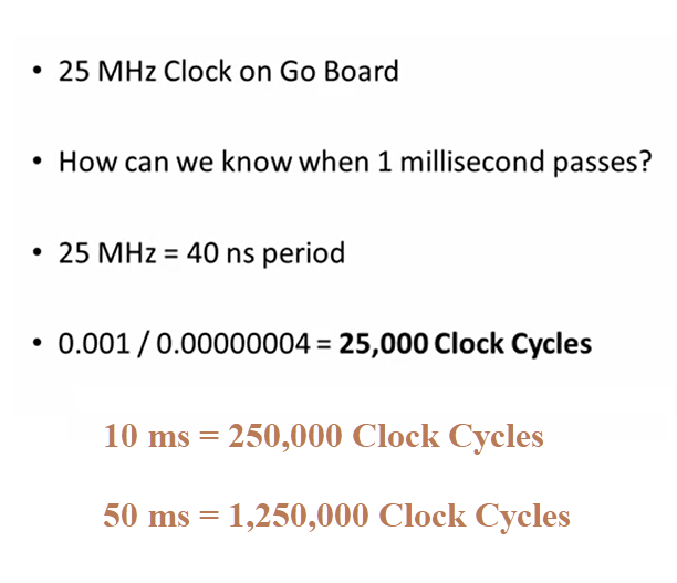
The d-flip-flop is linked to the external clock, and so is "fired"
every 40 ns (the external clock is 25 MHz, so if you divide 1 second
by 25,000,000 cycles, you'll find 0.000000040 sec per clock cycle).
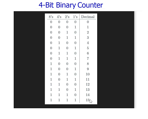
D-flip-flops can be linked together to build a counter, since they
maintain state, each can be a 1-bit digit of a larger number. Here's
an example of a 4-bit counter, which can count from 0 to 15:
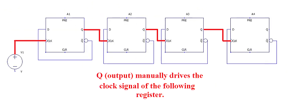
Here is how the registers are connected:
- First connect each Q output to the next Clk input.
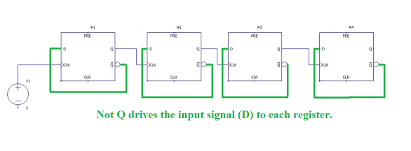
- Next connect each ~Q output back to the same register's D input.
If we just used 4 bits (4 registers connected this way), it would count
from 0 to 15 in just 0.00000064 seconds (640 ns, the result of 40 ns x 16 cycles)
The question is, how many bits would be needed to count up to 10 ms?
How many cycles are in 10 ms, if each cycle takes 40 ns?
From the image above, you see that 10 ms would require counting up to 250,000 cycles.
How many bits are required for this?
- 2^4 = 16
- 2^17 = 131,072
- 2^18 = 262,144 <--- this will work
- 2^19 = 524,288
18 bits would do it (18 registers wired together).
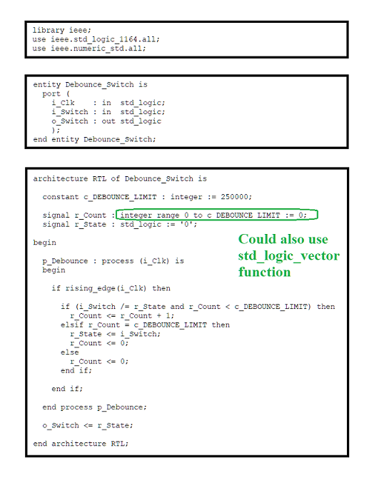
Implement "Debounce Switch" Component
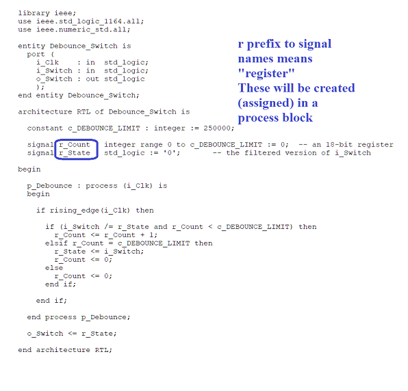
Registers are "created" in VHDL by being assigned to in a process
block (one that is clock driven, but having a clock signal in it's
sensitivity list).
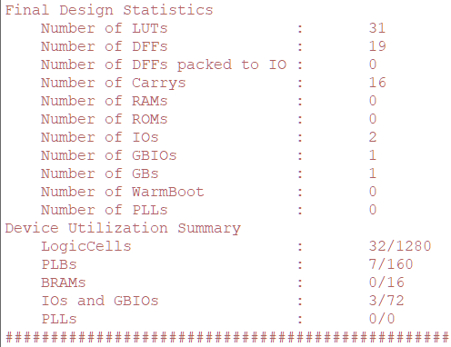
Looking at the final design, it may be surprising how many LUTs are
consumed. Most of these are needed to implement the compartor logic
in the line "if r_Count < c_DEBOUNCE_LIMIT". In order to compare values,
quite a few gates are needed.
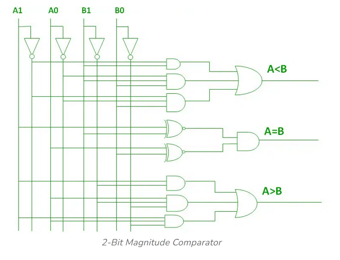
Here's an example of a comparator that is comparing two 2-bit numbers.
If this many gates are needed for just 2-bits, you can imagine how many
will be needed to compare two 18-bit numbers.
Solution Files: