Day 3's Project: lighting up the LED set attached to PortA in such a way
that when the Explorer 16 board is moved quickly back and forth, a message
will appear in big letters.
Day 4: Numbers
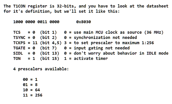
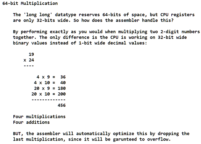
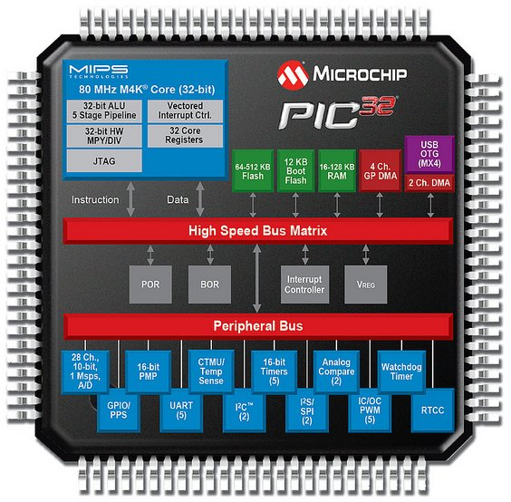
The PIC32 has 32 registers (32-bits wide), and a 32-bit ALU.
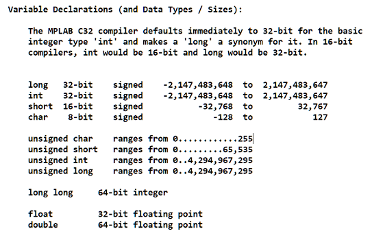
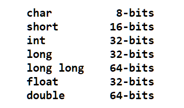
The MPLAB C32 compiler assigns the following bit-sizes per datatype:
As far as PERFORMANCE, the 32-bit CPU can work as effienctly on 8, 16,
or 32 bit values (one cycle each for math operations, thanks to the MMU
and MDU units in the PIC32). 64 bit values will take a slight performance
hit though.
As far as RESOURCES (limited RAM), datatype choices have direct
consequences. For example, 8-bit values (char) only take up 1 byte of
memory, not 4.
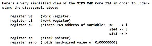
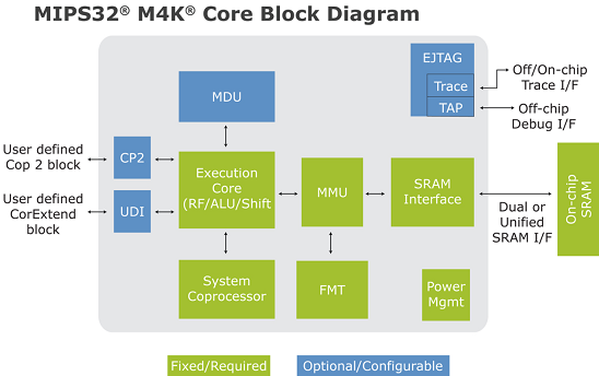
MIPS M4K Core ISA
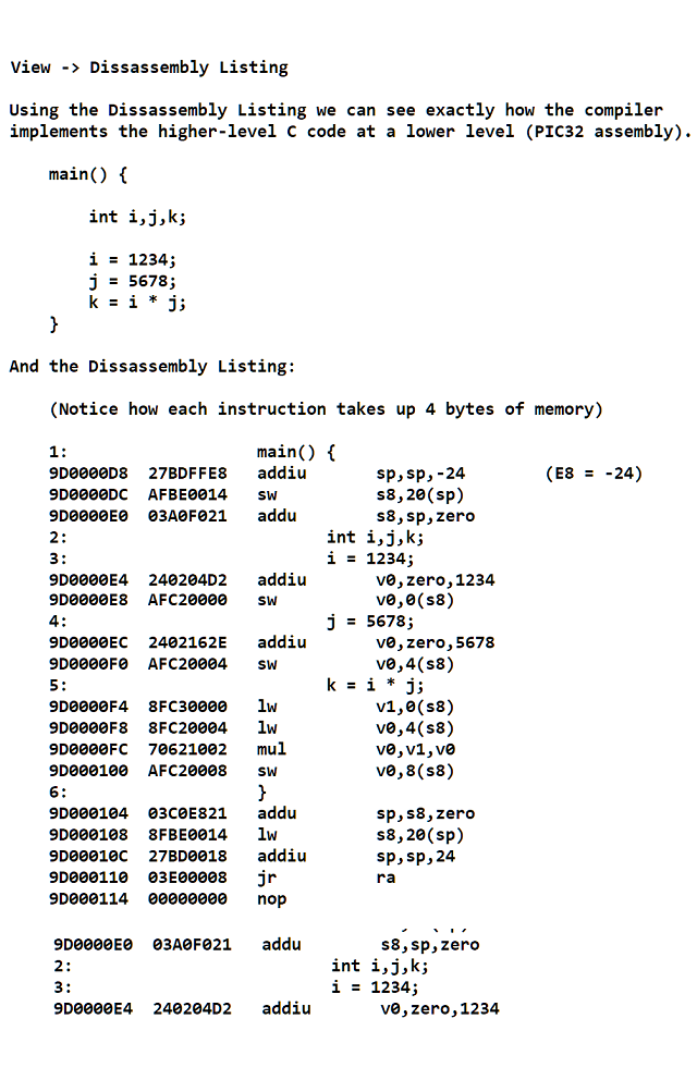
To make sense of the disassembled code above, knowledge of the MIPS
M4K ISA is needed. Like all other ISAs, this defines the number of
registers, their definitions/names, the instruction types and
instruction encoding, as well as the overall architecture such as the
LOAD-STORE architecture MIPS uses.
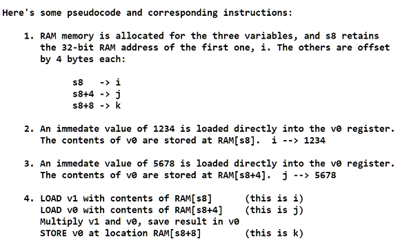
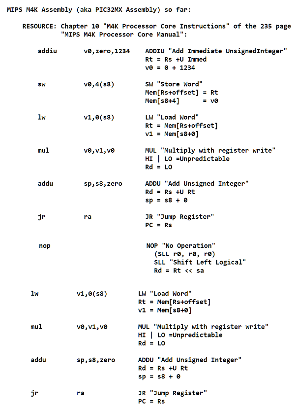
The LOAD-STORE architecture is also known as "register-to-register"
architecture. Basically, it means all operations (math/logic) are
performed only on REGISTER contents, and so to work with RAM, values
must be brought in from RAM (LOAD) and results must later be stored
back into RAM (STORE).
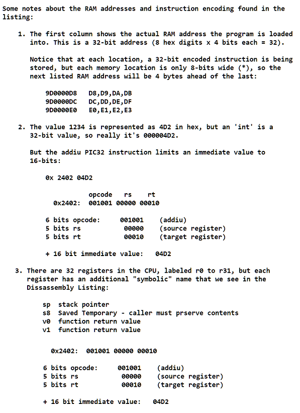
Review of Instruction Format Fields:
- opcode 6-bit primary operation code
- rd 5-bit specifier for the destination register
- rs 5-bit specifier for the source register
- rt 5-bit specifier for the target (source/destination)
register or used to specify functions within
the primary opcode REGIMM
- immed 16-bit signed immediate used for logical operands,
arithmetic signed operands, load/store
address byte offsets, and PC-relative branch signed
instruction displacement
Stepping through a Program:
- You can single step through the assembly code if you are in the Listing
window, or you can single step through the C code if you're in the
editor window.
- In both cases, you can view several things:
- Watch (shows you internal CPU registers)
- Local Variables (shows you variables in the C code, their values)
A note about Reset:
-
When you want to reset the program:
Debugger -> Reset -> Processor Reset
-
Note that this doesn't clear RAM or all RAM contents, so variables
will retain their previous values!
Integer Division (32-bit vs. 64-bit)
32-bit division can be handled directly, with a single div instruction.
64-bit division will rely on a subroutine:
libgcc2.c (found in MPLAB C32 directory)
Floating Point Numbers:
Regardless of 32-bit (float) or 64-bit (double, long double), the
MPLAB C32 compiler will use library calls (and expensive ones at that)
to perform math operations on floating point numbers.
Measuring Performance:
-
Debugger -> Stop Watch
-
Do this after compiling and linking a project. Then, single-step
through the program and the Stop Watch will measure the time!
-
Time is in cycles, in microseconds:
Debugger -> Settings -> Osc/Trace
Compiler Defines Data Size:
-
The older microcontrollers (16-bit PIC and dsPIC) used an older
compiler, MPLAB C30.
-
The PIC32's compiler, MPLAB C32 assigns different widths for each
datatype. For example, 'int' is now 32-bits, another name for a 'long'.
-
In the older compiler (C30) an 'int' was 16-bits wide.
-
This makes porting code between compilers difficult, even though the
code is written in strict C.
-
There is a library inttypes.h that define exact widths regardless of
what compiler, for example:
- uint16_t will always be a 16-bit unsigned integer type
- int32_t will always be a 32-bit signed integer type
Another useful library file, stddef.h, defines a datatype (size_t) that
will hold #bytes of another object. And there are many functions in the
string.h library that make use of that datatype, like the sizeof()
function.
MPLAB C32 supports other ANSI C libraries:
limits.h (holds size limits of all datatypes)
float.h (more size limits)
math.h (things liek M_PI)
Day 5: Interrupts
- Often microcontrollers can't afford the luxury of a multi-tasking
operating system. Interrupts are used to divide attention to different
tasks.
- C doesn't directly support interrupts, so you have to define special
functions to implement them. The MPLAB C32 compiler provides support
to take advantage of the PIC32's interrupt mechanisms.
- PIC32 = up to 64 distinct interrupt sources
Each can have an ISR (Interrupt Service Routine) defined
- The C32 compiler has libraries and language extensions to help.
MIPS core
- The MIPS M4K core handles "exceptions" by maintaining an ISR
vector table (a table of function pointers). Interrupts are
a type of exception:
divide by zero
reset command
access to memory that isn't there
- These ISR vectors can live in Data RAM or Program ROM, or
both, and the most important interrupts have default vectors
declared/defined at startup.
- Example Exception Sources:
Reset
On-Chip Debug (used by EJTAG devices)
Cache Error
General Exception
Interrupt
- Notice just one vector is assigned to "Interrupt". That function
uses a special register called "cause" to determine what triggered
the interrupt.
- The ISR will first save the execution process of the CPU, called
saving the "prologue", and be able to restore it, called the
"epilogue".
ISR for Interrupts:
- PROLOGUE (save processor state)
- query CAUSE
- EPILOGUE (restore previous state)
This central Interrupt vector can call any special ISR we define, using
the following rules for ISR function definitions:
ISR function return type void
No arguments allowed - parameter type void
These functions can't be called by other functions
These functions shouldn't call other functions
An example: One of the UART interfaces (there are 2), can generate any of
the following 3 interrupts:
- New data received and is available in the receive buffer for
processing.
- When data in the transmit buffer has been sent and the buffer
is empty, ready and available to transmit more.
- When an error condition has been generated and action might be
required to reestablish communication.
Up to 96 independent events can be managed by the PIC32 interrupt
control module.
So 96 sources, handled by 64 vectors
7 Control Bits per Interrupt
These are dispersed across several SFRs (of course they are).
- enable bit (all interrupts off by default) "Interrupt Enable"
- trigger bit (set when interrupt occurs) "Interrupt Flag"
- "Group Priority Level" ipl1, ipl2, ... , ipl7
The higher the priority level, handled first. The PIC32 itself
has a priority level kept in the MIPS core, and so the CPU will
ignore any interrupts lower than it's value (3-bits):
Core priority level = ipl4
Ignores any interrupts of level ipl1, ipl2, ipl3
- "Subpriority Level" 2 more bits
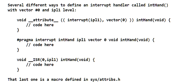
How to Define an Interrupt Handler in C:
Summary of Book (Topics):
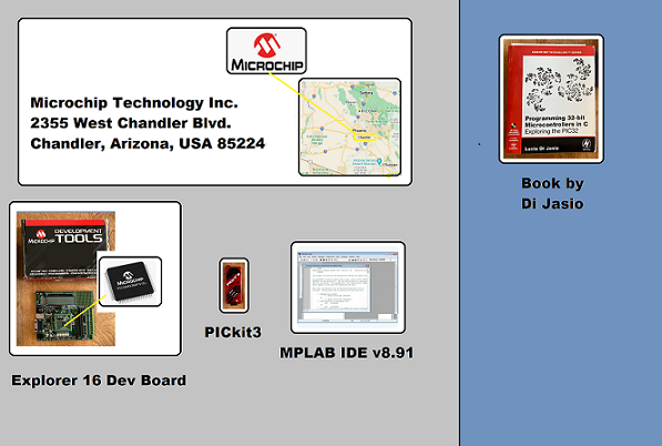
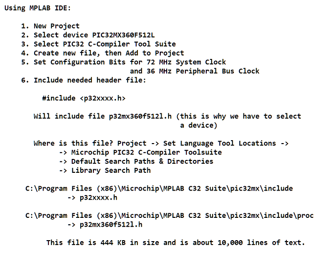
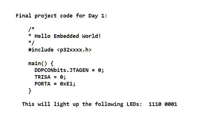
- Intro to hardware (PIC32 and Dev Board) and software (MPLAB). Hello World in C.
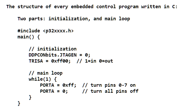
- Loops in C. How to use MPLAB's simulator (MPLAB SIM) and compiler (MPLAB C32).
- Datatype declarations, arrays, for and while loops in C.
- All numeric datatypes, MCU registers, Disassembly Listings, how division is implemented.
- Interrupts, interrupt handlers, functions in C, hardware timers.
- Memory, allocation techniques, Flash vs. RAM, strings in C, Memory Configuration Table, pointers, PIC32MX Bus and Memory Mapping.
- The Clock System and the Memory Cache System
- Communication peripherals (UART, I2C, SPI)
- Asynchronous Communication (RS232 interface)
- Interfacing with simple LCD screen
- Analog sensors
- Reading user input (buttons and sliders)
- Implementing NTSC video output
- Storing larger datasets onto SD Card
- File I/O (File System Implementation)
- Sound output (analog waveforms)
PIC32MX (Microcontroller Concepts Learned):
- Register set
- MPLAB usage and setup of initialization file
- How the 32-bit multiplier effects performance
- Memory management module
- Counting # assembly instructions (Disassembly Window)
- Counting instruction cycles (SIM StopWatch)
- Timers
- Interrupt system and Interrupt handlers
- Comparing efficiency of various numeric types
- The clock system
- Memory Cache system
- Protocols of basic communication peripherals (UART, I2C, SPI, RS232)
- Analog sensors, User Input, Video and Sound output
Back to Darron Vanaria's Portfolio